Programs and utilities for
generation of an ocean tide model.
Catalog of modules in library
liboteq.a at the end of this document.
Utilities: c.f. OTEU.DOC,
chapters I and II.
-----------------------
º MAIN PROGRAM CREAM º
-----------------------
CREate A Model
CREAM requires an instruction
file CREAM.INS to be placed into a subdirectory,
the ModelSubDirectory. The file
is read via unit 4. The MSDir will hold all
data files related with a
specific area as modelling will proceed.
�
Job phases: The model creation
job consists of the following phases:
-----------
Phase Task
1a Take the >Area
Outline<, spherical quadrangle bounded by integer
latitudes/longitudes and project
it to the plane. The system
determines a plane that encloses
this region completely. Grid boxes
back-projecting outside the Area
Outline are normally flagged
"Land" (except under
>Tiled< >Entire< area.
System assembles a first
'Z'-flags array, the >Raw Flag array< from
a temporary depth array on the
'Z'-grid.
1b Assembling the
>Depth Array< on a temporary 'M'-grid.
Optional
interactive
inspection of the depth arrays.
1c Optional output
of Raw arrays: Goto 7 and stop
1d Alternative to
1a+b: Input of previously saved Raw Arrays.
2a User supplied
update of land/sea ('Z'-grid) and depth array
('M'-grid) using UPDFLM (input from file unit 4).
Four depth values are affected
for each flag value. If this is
undesired, depth may be updated
in phase 3 instead.
2b Graphic display of 'Z'-flags together with GMT
coastlines
using procedure GRA_GLCOAST (glcopls.f).
Opportunity to update flag array
interactively, graphic screen.
Update parameters are output to
the protocol file (unit 7); they
can be used in subsequent CREAM
jobs, file unit 4, under (2a).
3 User
supplied update (file unit 4) of depth array,
exact location on 'M'-grid.
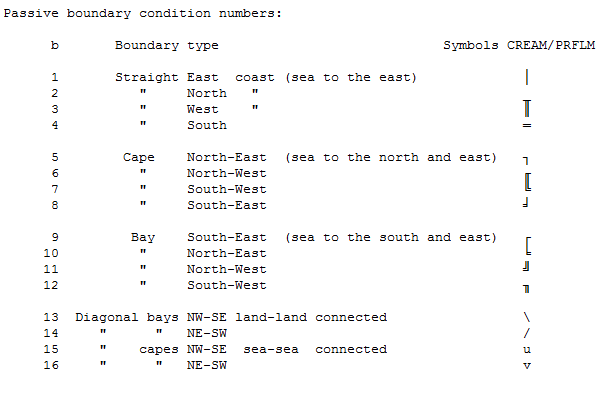
4 Assembling
passive boundary condition flags. User supplied data
is processed (file unit 4 / CONsole) indicating the style of
connectivity of land / sea in
diagonal directions.
The user is prompted at
locations of connectivity ambiguities
eventually remaining.
The interaction is via a graphic
interface. The
conflicts
are shown
on a zoom-in map.
There are two passes where the user
can enter the type of
connection. In the first pass, the
passive boundary conditions have
been devised up to the
conflict point but not beyond.
Thus, the grid may look a
little difficult to interpret.
In the second pass the
situation is more clear-cut.
Decision can be deferred to the
second pass by answering D
(Defer) or A (defer All). Otherwise
the user may enter Y or N
depending upon whether the pair of
cells is to be sea-connected or
not.
The answers are collected in the
MSDIR/prflm.prt file.
From there they can be copied
and pasted into the
CONNCT section of
MSDIR/cream.ins. If that resolves all conflicts,
CREAM will run quicker next time
(unless the user updates
the grid under 2b).
5 Assembly of
active boundaries (user supplied data on file unit 4).
This means: Injection of unresolved flags for Active Boundaries
and Out-Of-Area nodes, 'Z'- and
'M'-grids.
6 Display of
depth array using procedure GraSol;
interactive update of depth array using graphic screen:
Enter: Answer at GraSol-prompt
C x
where x > 0
Exit: Set STOP (enter S-key) at
GraSol-prompt.
7 Output
�
The
printed output
The file connected to unit 7 is
used for PRFLM, printing interpreted flag
arrays. 'M'-flags representing
land bridges are indicated by \ or /,
channels by u or v, for NW-SE or
NE-SW connections, respectively.
Passive boundary symbols are
intuitive.
Example:
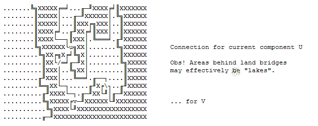
Side remark:
Example is Denmark. You realize
that an opening exists between mainland and
Fyn, whereas Store Baelt is
closed ! There is a lot of manual updating needed.
Baltic sea is to be closed off as
the area is too close to the right border
of the model.
--------------------
Side remark 2
There are opportunities to update
the depth array produced under (1b) at later
stages: Use ...
(1) interactive feature in TTEQ
/ OTEMT1. C.f. OTET.doc, OTES12.doc
(2) main program UPDEPTH.exp
(4) rerun Prep.2 phase,
OTEM92u.exp
(3) subroutine POKER, oteu013.f
File MSDir/cream.ins Structure
and codes
=========================================================================
Namelist &MODEL parameters:
_________________________________________________________________________
XLB,XUB,YLB,YUB (real*4):
Lower and Upper Bounds of the area:
X in
longitude, Y in latitude. Values in degrees.
SCALE
(real*4): Grid spacing in
kilometers.
SHORE, TOPMAX, HRESX, HRESY,
CFRSEA (real*4): c.f. routine ASSDEP
TOPODSC (char*64): Name of the
topo-bathy-descriptor file (default
/home/hgs/TOPO/topo.dsc) e.g.
/home/hgs/ETOPO1/topo.dsc
Qdbg_TOPO
.true.: extensive printing for each call of CTOPO
QASS
(logical): C.f. above, job
phases.
.true.: All job phases
.false.: Input "raw" arrays and do job phases 2...7
QSTOP
(logical): Stop after reading the
topo files (and QLOOK_H_).
QLOOK_H_Z
(log.) Interactive inspection of the depth array on
the
'Z'-grid.
QLOOK_H_M
(log.) Interactive inspection of the depth array on
the
'M'-grid.
QEntire_Area
(log.) The entire area is used (default =
.false.)
By default the area declared by XLB,XUB... determines the
exploitable parts of arrays. Due
to the projection of that
spherical area, dead land areas
will result along the edges
of the plane grids.
QTiled_Area
(log.) (default=.false.) under QEntire_Area=.true.
Outside the area outline, some 1x1 degree grid cells on the
sphere project partly outside
the plane grid. Use the Tiled-
area option to preserve only
"entire tiles"; grid boxes in
broken tiles will be flagged
"land". Yet, the amount of
"dead" land is much less than
with QEntire_Area=.false. The
area edges will be rugged as
they will line up with integer
meridians and latitude circles.
N.B.: This option must be backed
up with an (excessive)
pile of "Keep_Global_Land" alt.
"Keep_Global_Ocean" areas
in order to prohibit double
account of tide loading effects.
The Keep_Global_.. COMMON area
is presently too small for
this.
QShow_Coast
(log.) (default=.true.)
Show the coastline when the flag array is display for the
first time.
TEMPDIR
(char*64) (default=' ')
The directory to which GMT coastline dumps are made. An empty
string defaults to using
/home/hgs/GLCOAST. This catalog is
not open to strangers; they need
to create their own temporary
directory. There is a scratch
commons though. Use
TEMPDIR='/scratch/hgs/glcoast-dump/'
QSKIP_SHOW_CPROBLEM (log.)
(default=.salse.)
Don't show / don't prompt for decisions concerning
connection problems during pass
1 of Passive-boundary
detection at the stage of M-grid
assembly.
Instead defer decision to to
pass 2.
=========================================================================
INSTRUCTION INPUT
_________________________________________________________________________
Max 80 characters of comment.
_________________________________________________________________________
Namelist &MODEL
_________________________________________________________________________
File open block for input of
"raw" arrays (QASS=.false.), respectively
file open block for output of
"raw" arrays or final arrays (QASS=.true.)
file unit data type input/output
31 - 'Z'-flags and /CAREA/ I O
32 - 'M'-flags and depth I O
33 - Active boundary locations
(if phase 5 is nonempty) O
_________________________________________________________________________
File open block for output
(processed if QASS=.false., skipped if .true.)
_________________________________________________________________________
Saving raw flag arrays and exit:
Instruction: SAVE RAW
The system continues with phase 7
alt.:
Instruction: GRAPHIC
The system continues with phase 6
alt.:
Update sets for the Z-flag array
(transparent reading):
Instruction (1) UPDFLM
Instruction (2) N, skip-flag. N =
number of Update-instructions
until next instruction of type
(2).
Skip-flag Meaning
'T' Take
'S' Skip (=ignore)
'E' End of update sets.
Instructions (3..): Update
information to UPDFLM:
I1,J1,I2,J2,Flagvalue,Depth,'comment'
c.f. keyword UPDFLM below
_________________________________________________________________________
Updating the depth array at exact
location on 'M'-grid:
Instruction (1) UPDPTH
Instruction (2) N, skip-flag. N =
number of update-instructions
until next instruction of type
(2)
Instructions (3..): Update
information:
I,J,Depth,'comment'
_________________________________________________________________________
Connectivity information for
pairs of corners
Instruction (1) CONNCT
Instruction (2..) Y i,j - yes,
connect sea
N i,j - no, land bridge
(n) T - terminate CONNCT
_________________________________________________________________________
Injecting active boundaries:
Instruction (1) BOUNDZ
Instructions (2..) Boundary
parameter sets
c.f. keyword ABOUND below
_________________________________________________________________________
These instructions are difficult
(impossible) to anticipate. Most efficient
processing is:
(1) to execute with QASS=.true.
and SAVE RAW
(2) to execute with QASS=.false.,
retrieving the raw arrays, and using
trivial instruction sets under
UPDFLM, UPDPTH, CONNCT and ABOUND
(3) to iterate (2), building up
the instruction sets successively.
Hints are found in the protocol
file MSDIR/prflm.prt
Example: Med-Sea.
24 km grid interval, longitude
range 10 W... 37 E, latitude range 29 N ... 47 N
10x10 grid cell refinement to
interpolate depth
66% sea area required for a box
to obtain "Sea" status.
Do all job phases at once.
____________________________
START OF EXAMPLE ________________________________
Prep.step.1 of model OT12:
MEDITERRANEAN (new)
&MODEL
XLB=-10., XUB=37., YLB=29.,
YUB=47., SCALE=24.
HRESX=10., HRESY=10.
SHORE=-0.5,
TOPMAX=9.,
CFRSEA=-0.667
QASS=.true.,
qstop=.false.
&END
1 * Output files
case
QASS=.TRUE., input files case QASS=.FALSE.
7 B prflm.prt Protocol file
31 B MDL12/FLZRAW.DAT
32 B MDL12/FLMHRAW.DAT
33 B MDL12/ABOUND.DAT
Q
1 * This block is
bypassed due
to QASS=.TRUE.
31 B MDL12/FLZ.DAT
32 B MDL12/FLMH.DAT
33 B MDL12/ABOUND.DAT
Q
UPDFLM
9, 'T'
1,21, 3,26,0,-9999.,
'Mauretanian coast'
67,30, 75,33,0,-9999., 'Algerian
lowland'
126,10,183,16,0,-9999., 'Libyan
lowlands etc.'
182,23,183,33,0,-9999.,
'Israelian lowland'
183,55,183,55,0,-9999., 'Turkeian
lowland'
144,62,180,94,0,-9999., 'Black
Sea'
24,46, 24,46,1, 100., 'Strait of
Gibraltar'
24,45, 25,45,1, 200., 'Strait of
Gibraltar'
23,44, 23,44,1, 100., 'Strait of
Gibraltar'
25, 'T'
103,48,103,48,0,-9999., 'Messina,
Land'
104,47,104,47,0,-9999., 'Messina,
Land'
128,50,130,50,0,-9999., 'Korinth'
140,46,141,46,0,-9999., 'Kyklades'
138,48,138,48,0,-9999., 'Kyklades'
143,49,143,49,0,-9999., 'Kyklades'
92,78, 92,79,1, 3., 'Comacchio'
97,83, 97,83,1, 3., 'Trieste'
32,40, 32,40,1, 25., 'Melilla'
128,44,128,44,1, 75., 'Kalamai
Peloponnes'
182,60,128,60,1, 15.,
'Thessaloniki'
142,56,142,56,1, 15., 'Izmir'
143,37,143,37,0,-9999., 'Kreta'
141,36,141,36,0,-9999., 'Kreta'
135,38,135,38,0,-9999., 'Kreta'
131,43,131,43,0,-9999.,
'Peloponnes'
174,43,174,43,0,-9999., 'Cyprus'
149,45,149,45,0,-9999., 'Rhodos'
150,46,150,46,0,-9999., 'Rhodos'
149,42,149,42,0,-9999., 'Rhodos'
123,48,123,48,0,-9999.,
'Zakinthos Ionian'
123,50,123,50,0,-9999., 'Levkas
Ionian'
54,55, 54,56,0,-9999.,
'Ibiza+Formentera'
61,58, 61,58,0,-9999., 'Menorca'
87,43, 87,43,0,-9999., 'C.Bon,
Tunisia'
1, 'T'
101,38,101,38,0,-9999., 'Malta'
0, 'E'
UPDPTH
0, 'E'
CONNCT
N 86,28
N 87,43
N 150,43
N 174,43
N 150,46
Y 104,48
N 105,48
Y 123,49
Y 123,50
N 124,51
N 146,51
Y 133,53
N 144,53
Y 142,56
Y 143,56
N 141,60
Y 99,80
Y 100,80
T
ABOUND
W 20,64,17 "GIBR"
O 1,65,49,95
T
______________________________
END OF EXAMPLE ________________________________
ASSDEP: PARAMETERS and some
comments
============================
SUBROUTINE ASSDEP (H,FLM,TYPE,M,N,DEPTH,SHORE
&, TOPLND,RESX,RESY,CFRSEA,iuw)
Model construction * Make Depth
and Flag arrays
ASSDEP creates depth array H and
flag array FLM by calling the
EXTERNAL topography-function
DEPTH from north to south.
Border points (outside the area
determined by AOUTLI) will obtain
flag=100,000. Otherwise,
flag=0 for topography above
SHORE,
flag=1 below SHORE.
TYPE:
(char*1) An 'M' or a 'Z' type depth matrix (and accompanying
flag matrix) can be produced.
H(M,N): The
bathymetry grid (negative topography) is returned in H(M,N).
SHORE:
Topography values higher than this value (in meters)
are
taken as "land"; this affects the flag array and optionally
the H(i,j) values on "land".
A reasonable value is always
less than zero.
TOPLND: The value
which is to limit H(i,j) in case "land".
TOPLND
is of type topography (not bathymetry).
TOPLND
> 1E6 or < -1E6: ASSDEP will return H as the full
topographic
or bathymetric field.
RESX &
Resolution for obtaining mean depth values (in km).
RESY
If values of less or equal 0. or greater than SCALE (= the
grid
spacing) are used, default = SCALE will be taken,
which
means that the depth value
at the box centre is used.
Make sure
that RESX/Y is an
integer divisor of SCALE.
(SCALE is
specified to
subroutine AOUTLI.)
CFRSEA: Critical
fraction of sea content in a cell; discriminates
whether a
cell is counted "sea" or "land". Applies only
if -1E6
< TOPLAND < 1E6,
i.e. in "not-full topo/bathy" mode.
Specify a
value greater than 1
in order to obtain sea-land
discrimination on the basis of
average topography.
If CFRSEA
< 0 is specified,
the absolute of CFRSEA value is taken;
however,
average water depth is
only computed for the water
fraction
of the cell.
If
CFRSEA=0 is specified, one of
100 cells = sea is enough
to declare
the whole cell = sea;
pure land will be preserved
as land
however.
The
definition of SHORE is
applied after CFRSEA.
IUW
Protocol print log.unit
For use in preparation of OTEQ
depth and flag arrays, it is recommended to
(1) use CFRSEA = -.5 ... -.7
(2) SHORE = -10.
with the effect that average
depth is computed for the water-covered
fraction; if this depth is too
shallow, the cell is flagged "land".
Call Entire_Area (m,n) OTES811.f
prior to ASSDEP
to resolve depth array also
outside projected model area.
Then, ITOZ will require a wide
Grace limit !
UPDFLM: SPECIFYING UPDATE
PARAMETERS FOR FLAG ARRAYS
============================================
i1,j1,i2,j2,Flagvalue,Depth,'comment'
Set flag value in array from
south-west corner i1,j1 to north-east i2,j2
and set bathymetry to specified
depth value. The comment is printed on
the protocol.
Changing bathymetry only: Specify
Flagvalue=-9999
Changing flag value only: Specify
Depth=-9999.9
N.B.: CREAM.f calls UPDFLM on the
'Z'-flags and 'M'-depth arrays. This
implies that the four neighbour
nodes of bathymetry are subject
to change at each processing of
a flag node. In this mode, the
convention is that UPDFLM can
only increase depth.
If changes of bathymetry are
required at exact places, section
UPDPTH must be used.
Legal flag values:
Y/N Y/N indicates applies
to 'Z'-flags and 'M'-flags, respectively.
0
Land
Y Y
1
Sea
Y Y
10*b
Passive boundary
N Y
100,000
O_o_area
unresolved Y Y
-n
" storage ref.
Y Y
200,000
Act.bound
unresolved Y Y
200,000+10*b
" with pass.bound.cond. N Y
200,000-n " storage ref.
Y Y
n Storage reference, < 9000
b Pass.bound.cond. number
ABOUND: SPECIFYING ACTIVE
BOUNDARIES
============================
1. Summary
-----------
Processing a boundary = resolving
storage references at flags ("A")
P i1,j1,i2,j2 Protect a strip
when processing the next boundary.
The protected strip is limited
by the straight
line which connects (i1,j1) and
(i2,j2).
Boundary type N and S: i1 <
i2 is required,
" " E " W: j1
< j2
x i1,i2,j "NAME" where x = { N S
}: define north or south boundary from
i
= i1 to i2 at j = const.
x j1,j2,i "NAME" where x = { E W
}: define west or east boundary from
j
= j1 to j2 at i = const.
"NAME" is a unique name for each
boundary, enclosed in
double quotes. If no name is
given, a default name
"00##", ## = running number as a
string, is supplied.
The name can be used in TTEQ to
tweek
the boundary values (search for
_UPDAB).
New feature since Feb 2011.
Example
N 3,85,67 "NRTH"
goes from 3 to 85 eastward at j-position 67
E 3,85,67 "WEST"
goes from 3 to 85 northward at i-position 67
O
i1,j1,i2,j2 Change "Sea" into
"Out-of-area" in the rectangle
(i1,j1)
= Southwest corner, (i2,j2) = Northeast.
D n n >
0: Delete the last n
active boundaries
n <
0:
Step
up boundary index by n
T
Terminate
reading.
2. Codes and cases
------------------
(C1) Simple case.
Specify
x i,j,l
x = boundary orientation, i,j =
range from, to; l = location.
Boundary orientation = { E N S W
} (East, North ...)
Examples:
N 12,40,62 "NRTH"
meaning: Northern boundary, from
I=12 to 40 (eastward) at north 62.
Range and location are array
indices.
W 3,70,11 "WEST"
meaning: Western boundary, from
J=3 to 70 (northward) at east 11.
The Skagerak-Kattegat model
(KATT/cream.ins) runs such a simple case;
ABOUND
W 100, 180, 10 "WEST"
T
(C2) Difficult geometry.
ABOUND will turn "Open
Sea"-flags into "Out-of-area"-flags in the
region west of an active
W-boundary, east of an E-boundary etc.
Example:
........XXX,,,...XXXX
27
..........XXX,...XXXX
26
............XXX...XXX
25
..............aX...XX
24
..............A.....X
23
..............A.....X
22
Type N act.bound.
AAAAAAAAAAAAAAA...... 21
.....................
20
|
|
|
30
40
50
When the boundary is resolved,
the sea cells (".") to the north of it are
changed to "O", which affects
the model area at the locations marked ","
above.
In order to protect a model area
against the flag change, introduce
"protection polygons" before
defining the boundary:
P ib1,jb1,ie1,je1
P ib2,jb2,ie2,je2
... .... (max 10 polygone
sections can be handled).
A polygon section protects the
array cells behind it, seen from the
active boundary's vantage. It is
a line connecting start point (ibn,jbn)
and end point (ien,jen).
In the example above,
P 39,27,45,23
would be appropriate.
(C3) Left-over "Sea" cells to be
turned into "Out-of-area" cells.
ABOUND does not declare cells
"Out-of-area" if they lie north or south
of the end points of an 'E' or
'W' boundary, or - analogously - if they
lie west or east of the end
points of an 'N' or 'S' boundary. These cells
must be changed into "Out-of
area" by explicit instructions:
O i1,j1,i2,j2
Change "Sea" into "Out-of-area" in the rectangle
(i1,j1)
= Southwest corner, (i2,j2) = Northeast.
(C4) An active boundary can be
introduced temporarily.
Protection polygones can be
attached to a temporary boundary, i.e. a
boundary that is deleted again
after processing.
This facilitates the conversion
of "Sea" to "O-o-area" cells in those
cases were many O-instructions
would be needed.
3. Split jobs. First job
terminates after ABOUND.
Next job continues with ABOUND
and ABFLZ.
--------------------------------------------------
CREAM does not split these
phases. If reprogrammed, observe that...
The instructions for (C2) and
(C3) are passed to ABFLZ (entry in MKFLZ)
through common /CABOUP/.
The boundary location data (1) is
stored in common /CABOUN/. It can be
in-/output using GETAB / OUTAB.
The instruction D -1 can be used
after a set of P-instructions to
store protection polygones
without processing of any active boundary.
3. Examples
------------
(E1) The third boundary is to be
protected.
Instructions to ABOUND with
processing:
N 1,30,60 "N001"
N 50,55,65 "N002"
P 50,25,51,30
P 51,30,45,40
E 12,40,45 "EAST"
T
(E2) The third boundary is to be
protected.
Instructions to ABOUND without
processing:
Assume that three boundaries
have been declared earlier. They are already
represented in the flag arrays.
ABFLZ is to be rerun.
D 9999 Don't process any boundary
D -2 Assign next instruction(s)
to the 3'rd boundary
P 50,25,51,30 Introduce
protection polygones
P 51,30,45,40
D -1 Keep information for three
boundaries
T
Contents of library:
liboteq.a, context cream
(This is not really up-to-date)
Module:
otes41
Bathymetry,
internal routines
_depth_
fct. Bathymetry at a
random point
_extcdp_ fct. entry Extend buffer for
depth
Module:
otes71
Passive
boundaries, more or less obsolete.
_boundt_
subr. Bound.cond.numbers from
'M'-flags
_testsu_
" Used only
by BOUNDT
_mirr_
"
"
" " "
_rot_
"
"
" " "
Module: otes72
_boundz_iuo entry Output unit
for e.g. copying CONNCT requests.
_boundz_
subr. Bound.cond.numbers from
'Z'-flags; preferred.
_connct_
" Declare
connection status for land-land diagonals
Module:
otes81
Model
assembly, user's calls
_assdep_
Make
the bathymetry array
_aoutli_
subr. Define model area
_updflm_
" Update flag and depth array
_mkflz_
" Make 'Z'-flags from 'M'-flags
_abflz_
" Mark active boundary in 'Z'-flag
array
_abound_
" Mark active boundary and
determine 'O_o_area'
Module: otes811
_bentar_ block data /centar/
_entire_area_ subr. Depth resolved in
entire area (default: model outline)
_tiled_area_ entry Cut area borders
at integer degrees of sphere.
_enq_entar_ subr. Enquire
Module:
otes42
Bathymetry
file routines
_rtopo_
subr. Transfer data to a
spherical grid area.
_rtopo_e_ entry
...with alternate exit for EOF
_ctopo_
entry Continue transfer
_ctopo_e_ entry
... ... EOF
Module: glcopls
_gra_glcoast_ subr. Update flag array on
graph.screen. Disspla coasts
_cursor_upd_ subr. Cursor move and
prompt
.bye
Graphic
displays
2b GRA_GLCOAST
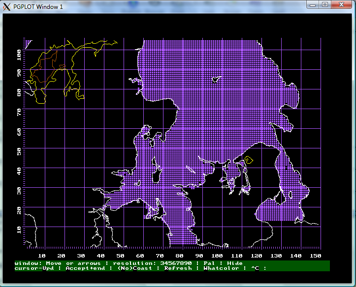
Above: This is the display of the
raw Z-flag array. After pressing U for cursor-Upd, ...
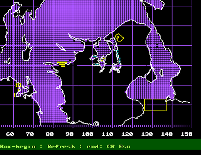
... a few changes have been made:
Yellow squares have been inserted to flip status to "Land" by
left-clicking a box and pressing L,
light-blue boxes to flip status
to "Sea". Finally, a rectangle has been started (yellow frame) to
introduce "Sea" into
southern Öresund by first
left-clicking on a box and pressing B to mark one corner, then
left-clicking on a box to mark
the diametric corner. Next S
should be pressed to indicate "Sea" as the new status. Then, the
Return-key will bring
the user back to the first menu bar, where A for accept can be pressed.
Or U to continue with updating (Sjællands Odde e.g.
should be turned into a chain of
land-boxes for instance).
There is no way to regret single
edits. The work done is not lost since the edits are written to the
protocol file
(prtflm.prt) from where they can
be copied-and-pasted into the instruction file (cream.ins). There is
nothing to get distroyed
either, since the raw flag array
is kept unchanged; thus, you can start all over.
Back to stages, 2b.
4 Diagonal dams and
straights
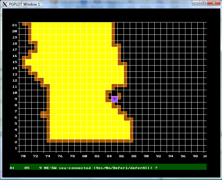
Defer = don't decide now.
Defer1 = this one problem.
The program can be configured
such that the first pass through the array is not shown. In the second
pass, the ambiguous connections
should all be resolved. To do this iteratively (no necessity, but still
there's this option) verifiable
decisions can be copied-and-pasted from the PRFLM.PRT file into the
cream.ins file. If the last
iteration of cream (successive runs of cream) is successful, PREP2 can
be
started (otem92).
Back to Phase 4